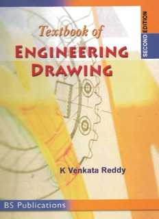
‘Textbook Of Engineering Drawing’ PDF Quick download link is given at the bottom of this article. You can see the PDF demo, size of the PDF, page numbers, and direct download Free PDF of ‘Engineering Drawing’ using the download button.
Textbook Of Engineering Drawing Pdf Free Download

Textbook Of Engineering Drawing
The distance between party’s corner and Egmore is 2.5 Km. On inspection of road map, its equivalent distance measures 5 cm. Draw a diagonal scale to read 50 meters minimum. Show on it a distance of 6350 metres.
Draw an inferior epitrochoid of base circle 150 mm diameter and rolling circle 50 mm diameter. The tracing point P is 20 mm from the center of the rolling circle.
(a) A square lamina of side 35 mm is parallel to HP with one of its sides is inclined at 30 to VP. The lamina is 20 mm above HP. Draw its top and front views and show its traces.
(b) Determine the locations of the following points with respect to HP and VP. (i) Point A whose front view is 70 mm above XY and top view 50 mm below
(i) Point B whose front view is 40 mm below XY and top view 55 mm above XY
(i) Point C whose front view is 45 mm above XY and top view 60 mm above XY.
4. A pentagonal pyramid of base side 40 mm abd axis length 80 mm is lying on the HP on one of its triangular faces with its axis parallel to the VP. It is cut by a plane inclined at 30° to the HP and perpendicular to the VP.
The cuttting plane meets the axis at 15 mm from the base. Draw the front view, sectional top view and the true shape of the section.
the axis of cylinder is 9 mm away from the axis of the cone and at a distance 30 mm above the base of the cone. Draw projection of the solids showing the curves of inter section between the solids.
A cylinder of base diameter 30 mm axis is 60 mm is resting centrally on a slab of 60 mm square and thickness 20 mm. Draw the isometric projection of the combination of the solids.
Lines (IS 10714 (Part 20): 2001 and SP 46: 2003)
Just as in English textbook the correct words are used for making correct sentences; in Engineering Graphics, the details of various objects are drawn by different types of lines. Each line has a definite meaning and sense to convey.
IS 10714 (Part 20): 2001 (General principles of presentation on technical drawings) and SP 46:2003 specify the following types of lines and their applications:
Visible Outlines, Visible Edges : Type 01.2 (Continuous wide lines) The lines drawn to represent the visible outlines/ visible edges / surface boundary lines of objects should be outstanding in appearance.
Dimension Lines : Type 01.1 (Continuous narrow Lines) Dimension Lines are drawn to mark dimension.
Extension Lines : Type 01.1 (Continuous narrow Lines)
There are extended slightly beyond the respective dimension lines.
Construction Lines: Type 01.1 (Continuous narrow Lines)
Construction Lines are drawn for constructing drawings and should not be erased after completion of the drawing.
- Hatching / Section Lines : Type 01.1 (Continuous Narrow Lines)
Hatching Lines are drawn for the sectioned portion of an object. These are drawn inclined at an angle of 45° to the axis or to the main outline of the section.
- Guide Lines : Type 01.1 (Continuous Narrow Lines)
Guide Lines are drawn for lettering and should not be erased after lettering.
- Break Lines : Type 01.1 (Continuous Narrow Freehand Lines)
Wavy continuous narrow line drawn freehand is used to represent break of an object.
- Break Lines : Type 01.1 (Continuous Narrow Lines With Zigzags)
Straight continuous narrow line with zigzags is used to represent break of an object.
- Dashed Narrow Lines : Type 02.1 (Dashed Narrow Lines)
Hidden edges / Hidden outlines of objects are shown by dashed lines of short dashes of equal lengths of about 3 mm, spaced at equal distances of about 1 mm.
the points of intersection of these lines with the outlines / another hidden line should be clearly shown.
- Center Lines : Type 04.1 (Long-Dashed Dotted Narrow Lines)
Center Lines are drawn at the center of the drawings symmetrical about an axis or both the axes.
These are extended by a short distance beyond the outline of the drawing.
- Cutting Plane Lines : Type 04.1 and Type 04.2
Cutting Plane Line is drawn to show the location of a cutting plane. It is long-dashed dotted narrow line, made wide at the ends, bends and change of direction.
The direction of viewing is shown by means of arrows resting on the cutting plane line.
| Writer | K Venkata Reddy |
| Language | English |
| Pages | 377 |
| Pdf Size | 17 MB |
| Category | Art, Engineering |
Related PDFs
Understanding Graphic Design Literacy PDF
Draw 50 Animals PDF With Simple Step
Building Construction Handbook PDF
Drawing Comics The Marvel Way PDF
Textbook Of Engineering Drawing Pdf Free Download
