‘Pipe Earthing Guide’ PDF Quick download link is given at the bottom of this article. You can see the PDF demo, size of the PDF, page numbers, and direct download Free PDF of ‘Pipe Earthing Electrode’ using the download button.
Pipe Earthing Diagram PDF Free Download
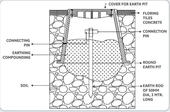
Pipe Earthing
The process of transferring the immediate discharge of electrical energy directly to the earth with the help of the low-resistance wire is known as electrical earthing.
The electrical earthing is done by connecting the non-current carrying part of the equipment or neutral of the supply system to the ground. It makes certain that all uncovered conductive elements do not get in touch with the perilous potential of the systems.
The earthing system cultivates to keep on the voltage at any segment of a power system at a specified value so as to prevent overcurrent or unwarranted voltage on the electrical device or apparatus [1], [3],[6]&[7].
A good characteristic of the electrical earthing aptly includes low permissible impedance to make sure that adequate current can pass through the protecting piece of equipment so that it isolates its supply within 0.35 seconds for secured safeguard purposes.
The fault current is characteristically higher than the full load current of the power circuit which liquefies the fuseor trips the breakers.
Features of Earthing
Good earthing systems will feature the following characteristics:
Good electrical conductivity Conductors capable of withstanding high fault currents Long life – at least 40 years Low ground resistance and impedance.
Importance of Earthing
The earthing is essential because of the following reasons :
The earthing protects the personnel from the shortcircuit current.
The earthing provides the easiest path to the flow of short circuit current even after the failure of the insulation.
The earthing protects the apparatus and personnel from high-voltage surges and lightning discharge.
Earthing can be done by electrically connecting the respective parts in the installation to some system of electrical conductors or electrodes placed near the soil or below the ground level.
The earthing mat or electrode under the ground level has a flat iron riser through which all the non-current-carrying metallic parts of the equipment are connected.
When the fault occurs the fault current from the equipment flows through the earthing system to the earth and thereby protects the equipment from the fault current.
At the time of the fault, the earth mat conductors rise to the voltage which is equal to the resistance of the earth mat multiplied by a ground fault.
The contacting assembly is called earthing.
The metallic conductors connecting the parts of the installation with the earthing are called electrical connections.
The earthing and the earthing connection together are called the earthing system.
TYPES OF ELECTRICAL EARTHING
The electrical equipment mainly consists of two non-current carrying parts. These parts are neutral to the system or frame of the electrical equipment.
From the earthing of these two non-current carrying parts of the electrical system, earthing can be classified into two types.(i)Neutral Earthing,(ii)Equipment Earthing.
NEUTRAL EARTHING
In neutral earthing, the neutral of the system is directly connected to the earth with the help of the GI wire.
Neutral earthing is also called system earthing.
Such type of earthing is mostly provided to the system which has star winding.
For example, the neutral earthing is provided in the generator, transformer, motor, etc.
EQUIPMENT EARTHING
Such type of earthing is provided to the electrical equipment. The non-current carrying part of the
equipment like its metallic frame is connected to the earth with the help of the conducting wire.
If any fault occurs in the apparatus, the short-circuit current passes the earth with the help of a wire.
Thus, protecting the system from damage.
Difference Between Earthing, Grounding, And Bonding
Earthing and Grounding are the same terms used for earthing.
Grounding is the common word used for earthing in North American standards like IEEE, NEC, ANSI UL, etc. while Earthing is used in European, Common wealthy countries, and Britain standards like IS and IEC, etc.
The word Bonding is used for joining two wires (as well as conductors, pipes, or appliances together.
Bonding is known as connecting the metallic parts of different machines that are not considered to be carrying electric current during normal operation of the machines to bring them to the same level of electric potential.
Different Terms Used In Electrical Earthing
Earth: The proper connection between electrical installation systems via conductor to the buried plate in the earth is known as Earth.
Earthed: When an electrical device, appliance, or wiring system is connected to the earth through an earth electrode, it is known as an earthed device or simply “Earthed”.
Solidly Earthed: When an electric device, appliance, or electrical installation is connected to the earth electrode without a fuse circuit breaker or resistance/Impedance, It is called “solidly earthed”
Earth Electrode: When a conductor (or conductive plate) is buried in the earth for an electrical earthing system.
It is known to be Earth Electrode.
Earth electrodes are in different shapes like conductive plates, conductive rods, metal water pipes or any other conductor with low resistance.
Earthing Lead: The conductor wire or conductive strip connected between the Earth electrode and the Electrical installation system and devices is called Earthing lead.
Earth Continuity Conductor: The conductor wire, which is connected among different electrical devices and appliances like distribution boards, different plugs, and appliances, etc.
in other words, the wire between earthing lead and an electrical device or appliance is called an earth continuity conductor.
It may be in the shape of a metal pipe (fully or partially), a cable metallic sheath, or flexible wire.
Sub Main Earthing Conductor: A wire connected between the switchboard and distribution board i.e. that conductor is related to sub-main circuits.
Earth Resistance: This is the total resistance between the earth electrode and the earth in Ω (Ohms).
Earth resistance is the algebraic sum of the resistances of earth continuity conductor, earthing lead, earth electrode, and earth.
| Author | – |
| Language | English |
| No. of Pages | 8 |
| PDF Size | 2 MB |
| Category | Education |
| Source/Credits | 5.imimg.com |
Budget Making Process In India PDF
Lesson Planning in Primary and Secondary PDF
How To Study ABROAD In Canada PDF
Unit 6 Max Weber Theory of Bureaucracy PDF
Pipe Earthing Diagram PDF Free Download