‘Alternating Current Class 12 Handwritten Notes’ PDF Quick download link is given at the bottom of this article. You can see the PDF demo, size of the PDF, page numbers, and direct download Free PDF of ‘Alternating Current Class 12 Handwritten Notes’ using the download button.
Alternating Current Class 12 Handwritten Notes PDF Free Download
NCERT Class 12 Physics Alternating Current
We have so far considered direct current (dc) sources and circuits with dc sources. These currents do not change direction with time. But voltages and currents that vary with time are very common.
The electric mains supply in our homes and offices is a voltage that varies like a sine function with time.
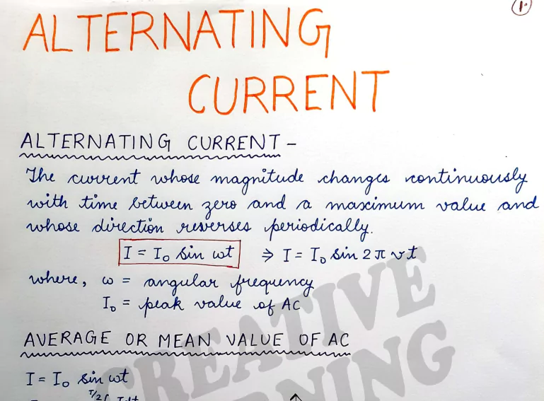
Such a voltage is called alternating voltage (ac voltage) and the current driven by it in a circuit is called the alternating current (ac current)*. Today, most of the electrical devices we use require ac voltage.
This is mainly because most of the electrical energy sold by power companies is transmitted and distributed as alternating currents.
The main reason for preferring the use of ac voltage over dc voltage is that ac voltagescan be easily and efficiently converted from one voltage to the other by means of transformers. Further, electrical energy can also be transmitted economically over long distances.
AC circuits exhibit characteristics which are exploited in many devices of daily use.
For example, whenever we tune our radio to a favourite station, we are taking advantage of a special property of ac circuits – one of many that you will study in this chapter.
- The phrases ac voltage and ac current are contradictory and redundant, respectively, since they mean, literally, alternating current voltage and alternating current.
- Still, the abbreviation ac to designate an electrical quantity displaying simple harmonic time dependence has become so universally accepted that we follow others in its use. Further, voltage – another phrase commonly
- used means potential difference between two points.
REPRESENTATION OF AC CURRENT AND VOLTAGE BY ROTATING VECTORS-PHASORS
In the previous section, we learned that the current through a resistor is In phase with the ac voltage. But this is not so in the case of an Inductor, a capacitor or a combination of these circuit elements.
In order to show the phase relationship between voltage and current in an ac circult, we use the notion of phasors, in t The analysis of an ac circuit is facilitated by the use of a phasor diagram.
A phasor is a vector which rotates about the origin with angular speed o, as shown in The vertical components of phasors V and I represent the sinusoidally varying quantities u and & The magnitudes of phasors V and I represent the amplitudes or the peak values u and of these oscillating quantities.
Figure shows the A phasor dia voltage and current phasors and their circuit in Fig Grapa relationship at time t, for the case of an ac source connected to a resistor i.e., corresponding to the circuit shown in The projection of voltage and current phasors on vertical axis. Le.
U sinet and (sinet. respectively represent the value of voltage and current at that instant. As they rotate with frequency a curves in Fig. 7.4(b) are generated. From Fig. 7.4(a) we see that phasors V and I for the case of a resistor are in the same direction. This is so for all times. This means that the phase angle between the voltage and the current is zero.
| Author | – |
| Language | English |
| No. of Pages | 36 |
| PDF Size | 25 MB |
| Category | Education |
| Source/Credits | Google.Drive.Com |

Related PDFs
Alternating Current Class 12 Handwritten Notes PDF